by David B. S. Smith
From L5 News, March 1980
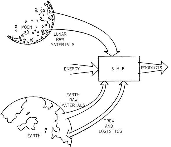
Figure 1: The Space Manufacturing Facility Concept
Between June 1978 and September 1979, the Massachusetts Institute of Technology (MIT) Space Systems Laboratory designed a space manufacturing facility. Under NASA research contract NAS8-32925, a three-volume study entitled Extraterrestrial Processing and Manufacturing of Large Space Systems was administered by the Marshall Space Flight Center. The Space Systems Lab (SSL) is a part of the MIT Department of Aeronautics and Astronautics, and includes professors and students in that department. This study also included one professor from the Department of Materials Science and Engineering, and one from the Department of Mechanical Engineering. However, most of the Lab consists of graduate and undergraduate students, and it is the students who were responsible for the bulk of the design work on the space manufacturing facility. This article describes some of the design procedure and the final output of the research [ref. 1].
The SMF Concept
The concept of the space manufacturing facility (SMF) is shown in Fig. 1. It is an in-space facility which receives most of its raw materials from the moon, some raw materials and logistics support from Earth, energy from the Sun, and produces components of satellites and large space structures. The SMF crew is rotated between the facility and Earth.
The study included the development of an SMF designed and sized to produce one 10-GW Solar Power Satellite (SPS) per year. The SPS design used was the NASA Johnson Space Center-Boeing Aerospace concept [ref. 2] (silicon solar cells, no concentrators, microwave beam production by klystrons and wave-guides), with the substitution of lunar materials wherever possible. The output of the reference SMF is therefore roughly 100,000 tons per year. Of this total, roughly 4,400 tons are materials and components brought from Earth; an additional 3,400 tons of Earth components are added to the SPS during assembly. Thus the lunar-material percentage of the completed SPS is roughly 90%. Although the products were keyed to the SPS, many of these components could be used in other satellites and space structures, and several are representative of sophisticated devices one might use in satellites. Therefore the reference SMF is an example of a widerange of space manufacturing.
Table 1 lists the SMF inputs. The materials brought from Earth are either undiscoverable on the Moon, or are components too difficult to manufacture in space. The difference between the total input mass (150,000 tons) and the total output mass (100,000 tons) is due to process wastage, either losses during manufacture or rejected substandard output. Some of this waste is converted to radiation shielding for space facilities.
TABLE 1:
REFERENCE SMF INPUTSFrom the Moon
Aluminum: 44000 tons
Iron: 1700 tons
Silicon: 27000 tons
S-glass: 1500 tons
Silica: 50000 tons
Natural Lunar Glass: 18000 tons
Magnesium: 180 tons
Subtotal: 143000 tonsFrom the Earth
Klystron Parts: 3500 tons
DC-DC Converter Parts: 700 tons
Kapton Tape: 420 tons
Foaming Agents: 240 tons
Dopants: 21 tons
Subtotal: 4900 tonsTotal Mass of Material Inputs: 150000 Tons
It should be noted that the study was strictly limited to design of the SMF only. The research did not include the lunar base (mining and refining operations), the SPS assembly station (separate from the SMF), or the transportation systems between these various locations. In fact, the orbital location of the SMF was unspecified (although geosynchronous orbit seems a likely choice).
To simplify the input systems for the SMF, the study group assumed that materials were delivered in convenient shapes (rods, slabs, bags of powder). This suggests rocket launch from the Moon. However, the SMF can accept pellet or block inputs with minor modifications.
Another guideline for the study was that no detailed design of the SMF habitat be attempted, since a number of habitat designs are detailed in the literature. This literature, together with some redesign work, was sufficient to cost-estimate the habitation.
A more important constraint on the SMF design is the use of the Johnson Space Center-Boeing designs for the output SPS components. These designs were optimized for Earth manufacture and launch, and therefore caused some complications in space manufacture. Redesigning the SPS components for ease of space manufacture could simplify the SMF design; however this was not done in this study. These assumptions and restrictions were necessary to keep the study manageable, within the time and money constraints of the contract.
Design Procedure
The group first listed a variety of tasks likely to occur at an SMF (e.g. alloying of materials, production of sheet stock, manufacture of structural members, manufacture of glass products, fabrication of solar cells). A catalog of possible processes was then developed for each task, listing process descriptions, advantages and disadvantages. These processes were themselves then broken down.
The investigation of alternative processes was largely done by undergraduate students, because the research team found that undergraduates were more likely to suggest unconventional processes, unattractive on Earth but promising in the different physical and economic environment of space. In a contract stressing new concepts and
“thinking zero-g,” the fresh approach of undergraduate students in many cases proved invaluable.
Based on the knowledge of candidate processes, the research team then designed the reference SMF. The first step was to develop operations layouts for the facility. The “SMF” box in Figure 1 includes five principal subsections: an input/output station; a set of factories which does the production work; a habitation section which houses the onsite personnel; a power plant which feeds electrical power to all sections of the SMF; and production control (more a function than an actual facility) which manages the operations of the entire facility.
The reference SMF can he conceptually separated into three factories: the solar cell factory, the waveguide factory, and the remaining operations grouped into the “components” factory. This separation is possible because each factory has its own set of material inputs and process equipment, different from those of the other factories (e.g. the materials and equipment used in solar cell production are unlikely candidates for the production of other SMF outputs). Within the component factory, however, materials and equipment are shared among a variety of products, to minimize equipment requirements.
Each of the production groups was then expanded in a detailed operations layout, showing individual types of machines. The massflows of materials through the various machines could then be calculated, thus sizing the equipment. One interesting observation from this sizing was that the components and waveguide factories (total yearly outputs 44,000 tons and 12,000 tons, respectively) are very small by Earth standards. The equipment sizes in those factories resemble pilot-plant equivalents on Earth. The opposite is true, however, of the solar cell factory. Its production rate (110 square kilometers, 44,000 tons/year) is roughly two to three orders of magnitude higher than current Earth production. The development of such a factory is therefore the largest technical challenge in SMF design. The candidate processes for solar cell manufacture were therefore studied in depth, with particular emphasis on development of processes which would take advantage of environmental factors peculiar to space.
The Reference SMF
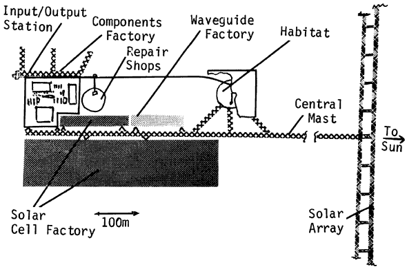
Figure 2: Plan View of Reference SMF
Following the operations layouts and equipment sizing, the study group produced preliminary designs of the individual SMF machines. These designs were then integrated into an overall physical layout of the facility (Fig. 2). The factories are essentially planar, i.e. the thickness of the equipment (into the paper in the figure) is on the order of 10-20 meters. At the right is the solar array, which is perpendicular to the plane of the factories, and which shields the SMF from direct sunlight. From the solar array extends a central trusswork mast. The habitation section and the factories are attached to this central mast via flexible joints; damping systems in the joints prevent the spread of vibrations, particularly in the solar cell factory. The solar cell factory appears large because several production steps use deposition processes which require large areas. The input/output is sized to hold cargo containers carrying four months of SMF inputs and outputs, and personnel modules for crew rotation.
The planar arrangement was chosen for two reasons. First, it makes access to the machinery relatively easy, for input and output of materials and for maintenance and repair. Second, it simplifies the removal of heat from the factories by allowing planar radiators above and below the equipment. The machines’ radiators are not shown in Figure 2, but they cover the top and bottom surfaces of the factory plane almost completely, and therefore serve as micrometeorite shields as well. It should be noted that no attempt was made in the study to assess the effect of the geometry chosen on the structural loads, attitude control requirements, or overall costs of the system. However, since the masses of connecting structure and internal transportation systems were estimated as less than 15% of the SMF mass, the relative positions of the facility components does not appear to have a major impact on the cost.
The habitat is a cylindrical cluster of 28 Shuttle external tanks, shown partially hidden by one of its two radiators. The 440 crew members of the SMF are housed in zero-g, in 24 external tanks converted to “habitation modules.” The remaining four external tanks are “core modules,” containing some dining and recreation areas, and solar flare shelters. In addition, environmental control and life support system modules are nested between the external tanks. Shielding for the habitat is provided by lunar materials, and serves as an input backlog for the SMF, to be progressively replaced by process waste. The crew is rotated between the SMF and Earth, on a three-months-up/three-months-down schedule, to keep the radiation and zero-g effects within easily tolerated limits. The Earth-launched habitat hardware masses 1,300 tons, plus an emergency consumables supply of 67 tons. The shielding mass is 3,500 tons, and the consumables requirement is 178 tons/year. Of the 440 SMF personnel, 50 are machine operators, 170 are maintenance and repair personnel, and 220 are support personnel (supervisory, management, clerical, culinary, medical, housekeeping). These workers are organized in three shifts, and the SMF operates continuously. The average work week is therefore 56 hours, and at any given time one-third of each type of personnel are at work. The low number of machine operators reflects the high level of automation in machine control. Support personnel are set at 100% of the production personnel (machine operators plus maintenance and repair personnel). Thus the reference SMF has a productivity of 150 kg/production-person hour, high by Earth standards but possible (in the opinion of the study group) for a highly automated facility.
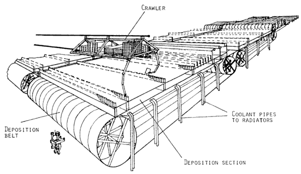
Figure 3: Overall View of Solar Cell Factory
For the solar cell factory, the study group devised a continuous production-line manufacturing system, using deposition onto moving belts. Figure 3 is a perspective view of the solar cell factory. The deposition equipment sits above and below the belts, and the solar cell layers are deposited as the panels are connected into array segments. The arrays are packaged and transferred to the input/output station. Figure 3 also shows a “crawler,” one of a series of devices which feed, maintain and repair the solar cell factory.
The reference SMF includes 266 production lines (19 groups of 14 lines each). Each line produces 1.1-meterwide solar cell panels at .85 meters/ minute. It should be noted that several of the processes suggested are highly experimental (specifically, the pulsed-beam recrystallization of silicon, and the direct vaporization of silicon and silica layers), and that the proposed sequence therefore carries a high technical uncertainty. However, the traditional methods of solar cell production appear too slow for SPS manufacture, and the SMF designer must therefore explore new methods.
Costs
The individual equipment designs were then tabulated on specifications sheets, one sheet per type of “machine.” There are roughly 60 different “machines” in the reference SMF, most with four or five components. Costing sheets were then developed from the specifications sheets. The costing sheets listed the machines’ and components’ cost-driving parameters, such as mass, power requirements, duty cycle, labor requirements, research and development (R&D) and procurement costs, and repair needs. For each machine these quantities were defined through literature search, consultaions with experts in the field, and preliminary design calculations. R&D costs were estimated according to a low, medium, high or ultra-high technology rating on the components.
The data from the costing sheets adds up to some 3,000 numbers impacting overall SMF costs. This data was input to a line-item, costing computer program which calculated nonrecurring and recurring costs of the SMF, including computation of personnel totals, logistics, power and consumables requirements, mass totals, transportation requirements, and their associated costs. A summary of the reference SMF costs appears in Table 2. It should be emphasized that these numbers are very preliminary, and strongly affected by the assumptions made in the analysis. One critical parameter identified (by using the line item costing program for variation of parameters) is machine reliability. There appears to be a cost minimum corresponding to a failure rate roughly twice that of the reference SMF; thus the SMF designed in the study seems slightly over-engineered.
TABLE 2:
REFERENCE SMF COST SUMMARY
(All Costs in 1979 $)Non-Recurring Costs (costs of establishing the system): $11.6 B
Recurring Costs (Costs of operation): $1.2 B/Year
Net Present Value Cost of SMF (Assuming 10% discount rate,
20-year operation, one 10-GW SPS per year production): $22.0 BNet Present Value Cost of SPS Manufacture (SMF operations only, one 10-GW SPS/year for 20 years, 10% discount rate; does not include lunar operations, lunar materials transportation, SPS components transportation and assembly): $1.1 B
The space environment appears to lend itself well to the development of a space manufacturing facility, with most operations improved rather than hindered by vacuum and zero-g. Such a facility, using lunar-material inputs, could be cost-effective when producing outputs with a total mass on the order of an SPS. However, the economic viability of the total system, including the lunar base and transportation systems, has not as yet been established.
Further detailed study of the SMF is needed to establish optimum tradeoffs in product and equipment design, production control strategies, maintenance and repair strategies and redundancy levels, and to produce more accurate estimates of total personnel needs. Much of the research and development of SMF equipment can be done on Earth. Experiments and prototypes flown on the Shuttle can be small, but may benefit from the availability of an orbital platform providing electrical power, waste heat radiation, and in-space storage of equipment.
Conclusions
1) SMF is technically feasible.
2) SMF production sequence appears versatile (wide variety of products), flexible (wide variation in production rate), and productive.
3) The space environment suggests specialized SMF processes which might not be practical on Earth; examples of such space-specific processes are direct vaporization techniques, electromagnetic melting and containment, and electron beam cutting and welding.
4) There are economic advantages in tailoring design of SMF products for ease of space manufacture.
5) Evaluation of the lunar-material option requires more in-depth systems studies, trading off the various scenario parameters (e.g. characteristics of lunar base, transportation systems, SMF, assembly station and output SPS).
6) Technology demonstration programs are needed to verify suggested processes. In-space prototypes need not be large, but can benefit from a permanent orbital platform.
7) Based on 1 SPS/year the SMF will require nonrecurring costs of $11.6 x 10⁹ including R&D, procurement, transportation and power supply, annual recurring costs of $1.2×10⁹ will be required and an operating crew of 440.
References
1. R.H. Miller, D.B.S. Smith, et al, Extraterrestrial Processing and Manufacturing of Large Space Systems, Final report, NASA contractor report CR-161293, September 1979.
2. Recommended Preliminary Baseline Concept, SPS Concept Evaluation Program, NASA Johnson Space Center, January 25, 1978.
Dave Smith is with the Massachusetts Institute of Technology Space Systems Laboratory. The NASA study to which this article refers is available here.
