demanditea
mare-low Ti
required
 -.0569
-.2951
-.0569
-.2951The Initial Lunar Supply Base
DAVID R. CRISWELL
The initial lunar supply base should have a mass less than 1000 tons, be deployed by 25 persons in 4 months, and be maintained by 10 persons. Output could be expanded 20 times in 5 years to 600,000 tons/yr by a factor of 10 expansion of the area of the solar array on the lunar surface, using low power soil beneficiation, increasing the fleet of mining vehicles, and illuminating the base continuously at night with lunar orbiting mirrors. The space manufacturing facility (SMF) will supply most of the mass (solar cells and orbiting mirrors) necessary for expansion. Several devices and procedures are suggested for development which could further reduce the total mass necessary to transport to the Moon to establish the initial lunar supply base.
INTRODUCTION
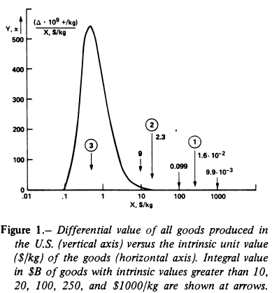
The ultimate objective of space industrialization is to create a growing economy in space which can eventually become self-sufficient. Space industry is presently supported by sales of goods with extremely high intrinsic values, such as satellites for communications, research, navigation and reconnaissance. Low-volume production of exotic goods in the zero-gravity and weightless conditions afforded in near-Earth space may broaden the market for space produced goods. However, in all these cases the cost of transporting the goods or raw materials into low-Earth orbit will add $200-$700/kg to the product price for a period of 15 years and thus place a sharp limit on the ultimate terrestrial market (ref. 1). There appears to be a way of circumventing the present high cost of launching materials from the Earth into space. This can be done by acquiring bulk raw materials from the Moon or asteroids and processing them in space into economically valuable products. Initial bulk material costs could be of the order of $25/kg in high-Earth orbit (see Salkeld appendix)and the cost would drop with experience. There would be two effects of lower material costs. First, the space economy could begin approaching the richness and cost structures of our present terrestrial economy. Secondly, the range of space products that could be sold for terrestrially-related use either in space or on Earth would be greatly expanded.
The Moon can supply most of the mass needed for large-scale industry in space. There are two ways to approach the proof of this statement. The first is to look in detail at the materials needed to construct specific products in space. At this point in time the production of space solar power stations is an attractive candidate because of the high value per unit mass of such objects and because of the large number of stations which could be required (>200 in next 30 years). Analyses even of designs not optimized for lunar elements reveal that at least 60 percent of the required silicon, aluminum and oxygen could be obtained from the Moon and the total mass lifted from Earth could be reduced about 80 percent by utilizing lunar materials (refs 2 and 3).
Alternatively, one can compare the nonfuel distribution of nonrecoverable elements (weight fraction) utilized in the industrial economy of the United States with elements present in the lunar soil as is shown in table 1 (ref. 4). The fraction of these elements which can be extracted with reasonable and presently available chemical processing techniques from beneficiated lunar ores is the subject of two companion papers (by Williams et al. and Rao et al.respectively) discuss extraction of Si, O, Fe, Al, Ti, and H2O. Using these and other proposed extraction procedures most of the components of the synthetic molecule of "Demandite" (defined in table 1), which constitute most of the nonfuel material inputs to American industry, could be provided in deep space at less cost per unit mass than the launch cost of the complete suite of the constituent elements directly from Earth in large tonnages until the mid-1990's (ref. 4).
| Nonfuel demanditea |
Apollo 15 mare-low Ti |
Enhancement required |
Bulk soil (1 unit)b | ||
|---|---|---|---|---|---|
| Si | 0.2444 | 0.2158 | 1.13 | -- | 0.0286 |
| O | .4547 | .4130 | 1.10 | -- | .0417 |
| Fe | .0479 | .1535 | .31 | 0.1056 | -- |
| Al | .0023 | .0546 | .04 | .0523 | -- |
| Mg | .0017 | .0681 | .025 | .0664 | -- |
| (Cu, Zn, Pb) | .0020 | 2.2 (-5)c | 90 | -- | .0020 |
| Xd | .0030
-.0569 |
0.0189
-.2951 |
.15 | .0159 | -- |
| Cae | .1417 | .0696 | 2.0 | -- | .0721 |
| Na | .0095 | .0023 | 4.1 | -- | .0072 |
| S | .0058 | .0006 | 9.7 | -- | .0052 |
| Ke | .0021 | .0008 | 2.6 | -- | .0013 |
| Pe</</TD> | .0019 | .0005 | 3.8 | -- | .0014 |
| Cl | .0147 | 7.6(-6) | 1934 | -- | .0147 |
| Ne | .0083 | 8(-5) | 103 | -- | .0083 |
| Ce,f | .0574 | 9.5(-5) | 604 | -- | .0573 |
| Hf | .0025 | 6.4(-5) | 350 | -- | .0025 |
| Otherg | .0001 | .0023 | .03 | .0022 | -- |
| 1.000 | 1.000 | -- | (+)0.2424 | (-)0.2423 | |
 10N
10N )
)Notice in column 4 of table 1), that the major demandite components (Si, O, Fe, Al, Mg, X, Ca, Na, K, P, and S) are present either in adequate concentrations or in enrichments that are 10 times the specific fractions of the soil. Beneficiation of soil components to enhance and possibly simplify. known chemical extraction processes should be achievable using electrostatic, magnetic, dielectric and mechanical techniques and careful site selection. Elements such as Cu, Zn, Pb, H, Cl, N, C, and other trace elements comprise 8.4 percent of the demandite molecule. These elements would be shipped from Earth, eventually located from other sources, such as non-Apollo sites, or other materials substituted for them. In any event, it is clear that of order of 90 percent of the present day inventory of industrial elements can be provided from known lunar soils. Lunar soil processed to provide 90 percent of the demandite complement at $20/kg (i.e., Si, Al, Fe, Mg, Ca, and O) and the remainder supplied from Earth at $300/kg would provide the in-space demandite molecule at a cost of about $50/kg or 17 percent of the direct supply cost (ref. 4).
It is very clear, however, that substitution of materials, which is being required in the terrestrial economy even now, will permit much greater use of lunar materials both in general and for specific products (ref. 5). Thus, the cost of space "demandite" should approach the cost of the lunar processed materials.
The economic value to Earth of the Moon or the asteroids as a
source of raw materials is strongly dependent on the total
retrieval and elemental separation costs of the raw materials.
Figure 1 is a qualitative
description of the costs of goods or end-use-material on a dollar
per kilogram basis (horizontal axis) versus the differential output
of the total value of goods in the U.S. economy in billions of
dollars per dollar per kilogram or ( l09 $/($/kg))
for a total GNP of $1012
(ref. 1).
l09 $/($/kg))
for a total GNP of $1012
(ref. 1).
Most goods now sell for less than $10/kg with most between $0.1/kg and $2/kg. Transport into low-Earth orbit (LEO) from the Earth presently adds more than $500/kg and thus confines goods produced in space to a tiny fraction of the potential terrestrial market (right of arrow 1 in fig. 1). Solar power stations are estimated to be economically feasible at $140/kg (refs. 3, 6). Supplying the bulk of the required construction material from the Moon at $20/kg (arrow 2) would clearly improve the economics and decrease the cost of the power supplied to Earth. If sources of industrial feedstock can be developed in deep space with costs of less than $0.5/kg (arrow 3) then many of the Earth-produced goods can be considered for potential space manufacture (ref. 1). It is conceivable that industrial material can be supplied at such low costs from the Moon or asteroids assuming normal industrial "learning curve" experience occurs.
Previous scientific exploration of the Moon and the vigorous ongoing program of lunar sample research and theoretical analyses allows us to study and plan in detail for obtaining lunar materials and chemically processing them. However, additional research is necessary and should be an ongoing component of the lunar base siting and operation. A general survey of the Moon is necessary - including the polar regions. There should be a close tie-in of the lunar sample and planetary sciences communities, with the engineering communities responsible for research and development of lunar bases and refining schemes. Above all, design of the lunar supply base should be approached so as to minimize total cost and maximize output to provide useful components of the lunar soil at points in deep space at the lowest possible cost per unit mass.
The following sections describe one approach toward a lunar base of minimal size which could be expanded in launch capacity from 30,000 tons/yr (bulk soil) to 600,000 tons/yr (beneficiated soil components) over a 5-year period making maximum use of lunar materials to minimize shipping from the Earth.
It is a pleasure to acknowledge the support supplied by the NASA-Ames Research Center in organizing the logistics and operation of this summer study. Particular appreciation is expressed to J.Billingham, W.P. Gilbreath, and B. Zeitman. Interactions with other participants, far too numerous to offer personal thanks by name, were intellectually stimulating, demanding, and rewarding. I wish to specifically thank J. McCoy (Johnson Space Center), P. Vajk (Science Applications Inc.) and A. G. MacDiarmid (Univ. Penn.) for critical comments and suggestions concerning the text; deficiencies that may remain are of my own making. This work was conducted in part under NASA contract #NAS-09-051-001 to Universities Space Research Association which operates the Lunar and Planetary Institute (LPI). This is LPI Contribution No. 317.
LUNAR BASE TOUR
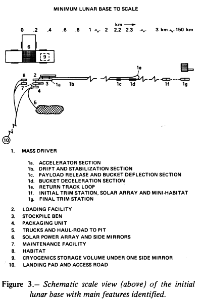
Conceptions of mankind's first permanent installation on the Moon have tended to evoke paintings of either immense facilities containing hundreds of persons and enormous traffic between the Earth and the Moon (ref. 7)or, on the other hand, simple and isolated extensions of the Apollo lunar module with little space, with limited capability and operated by ony three or four persons. Concepts evolved during this study project a different style - one dominated for at least the first 5 years by the severe demands of utility and cost effectiveness. The principal function of the base is providing a supply of minimally-processed lunar materials to a collection point in deep space at the lowest possible initial cost, greatest reliablity (attainable principally through simplicity of design) and with a straight-forward plan for expansion of base output capacity by a factor of 20 over 5 years.
Figure 2 is a painting of the initial lunar supply base during the second lunar day of installation. All maajor features except three large adjustable mirrors to the east, west and north of the solar array are depicted. Upon completion of the base, the three adjustable mirrors immediately to the east, west and north, dominate the scene. Figure 3 is a scaled schematic of the base which will assist in locating the components described in the following tour. The solar array (item 6 in fig. 3) is about 180 m on a side (10 percent efficient cells) with a mass of 108 tons. Each of the three side mirrors (180 m wide, 260 m high) is individually aadjustable to focus the maximum amount of sunlight on the solar array and catch the last glimpses of the Sun after local sunset. Most importantly, it focuses the reflected sunlight from two to four solettas (large mirrors orbiting the Moon)which provide the equatorial base at night with one-ninth the full solar illumination adequate initially to maintain continuous operation of the mining, maintenance, and life systems, but not mass driver operation. Each surface mirror can be elevated from the horizontal to face the solar array at 45o past the local vertical. Although visually imposing because of their enormous width, 70-story height, and constant visible tracking motion night and day, they are very flimsy and lightweight structures with a mass of 18 metric tons including hoists (estimated by E. Bock, study participant).
Lunar base is on the Earth side of the Moon near a juncture region between Mare Tranquillitatis and the eastward highlands. At night, a pinpoint of light 8.7 km across is centered on the base and is visible from Earth as a variable star in the dark disk of the Moon. Four large, multifaceted mirrors, each 8.7 km in diameter and 240 metric tons in mass and in lunar orbits that are continuously sunlit, can illuminate the base with reflected sunlight. These orbiting mirrors are named solettas (refs. 8, 9). Continuous tracking of each mirror allows each to be sailed in its orbit about the Moon using the pressure of sunlight, so as to maintain the apolune of each soletta directly above the lunar base during the night. As seen from the lunar surface, the mini-suns sequentially rise in the west, cross the vertical meridian just higher than 30o above the horizon, and set in the east just after the following soletta rises in the west. Thus, there is a continuous input of solar energy for power, locally warming the extreme cold of lunar night and providing illumination for mining. The initial solettas were assembled in low Earth orbit from terrestrial materials, and then solar sailed to the Moon and into lunar orbit prior to the first landing of the lunar base components. The reflective area is increased thereafter using aluminum and fiberglass produced at the space manufacturing facility (SMF).
This soletta approach seems awkward on first consideration. However, the orbiting mirrors can be constructed in low Earth orbit and solar-sailed to lunar orbit without using propellant. They may also be capable of transferring significant cargo on a one-time basis. Such capability is not examined in this paper. Of immediate interest is the fact that use of solettas allows one to eliminate the need for about 400 tons of power storage equipment (example - flywheels) for nighttime operation of the base and also the 280 tons of propellant necessary to land the power storage units. Thus, the mass one transports to low lunar orbit could be decreased from 2600 tons (table 2 of Vajk et al.,) to 1920 tons. It is conceivable that one can reduce the number of MDRE trips to deploy the base from LEO to LLO to two or even less by use of the solettas for illumination and possibly transport.
Restricting early mass driver operation to the lunar day, deploying a directable solar array and utilizing the solettas, enables continuous operations in construction and running of the base, minimizes the need for power storage and support machinery (the latter by a factor of 2) and greatly moderates the thermal day/night extremes at the lunar site.
Also visible from landing altitude is the 2-km-long 5-m-wide mound of excavated lunar soil which covers the top of the tunnel containing the mass driver (item 1, fig. 3). A very slight dogleg is visible 200 in from the far end where the 3.8 kg slugs of packaged lunar soil are ejected from the deaccelerating buckets (item le, fig. 3). Three kilometers beyond is the first "Drift and Stabilization Section" (item If, fig. 3). At the end of the dogleg is a 100-m-diameter loop wherein the buckets are turned around and returned on a passive guideway toward the main tunnel and the loading facility. Almost all other features of the base, including the initial strip mine (item 5, fig. 3) are difficult to discern because of their small size, the blending covers of lunar soil, and the visual confusion of permanent disturbance patterns in the lunar soil resulting from the emplacement of the base and ongoing vehicular operations.
Technical details of the mass driver are given in a companion paper. Here the concentration is on layout related to installation, volume, and mass. The major mass driver acceleration sections are assembled from 23 connected subsections. The coasting sections can be shipped in partially assembled condition to minimize shipping volume if necessary. All components of the mass driver system must be shielded from the extremely fine lunar dust. Thermal fluctuations must also be minimized to simplify design of the electronic and mechanical elements, maintain stable operating conditions, and prolong component lifetime. Radiation protection should also be provided for maintenance personnel. The MD system is laid out in a leveled trench 5 m wide, which is encased by heavy fiber reinforced Kevlar sheets laid directly on the lunar soil in the trench and supported on the side walls and ceiling by graphite epoxy stays (20 in formed hoops of 1 cm' cross section) every meter down the tube. Small openings are provided for ejection of the slugs and escape of gas from space suit and repair operations. The stays and Kevlar mass is less than 20 metric tons. Lunar soil is heaped over the sides and top of the trench to a thickness of 4 in (300 g/cm2 column density) thus providing an extremely stable thermal environment of < �1 K (ref. 10) and complete radiation protection for repair and maintenance workers Portable pressure chambers are provided which can be set up wherever in the tunnel detailed repair or mainte nance is required. Accelerator sections can also be unplugged and rolled down the tunnel to the maintenance section.
Bags of lunar soil ( 3.8
kg) are ejected by the mass driver ftom the Moon. Downrange
adjustment of the ejection velocity (i.e., velocity trimming) is
accomplished by means of two trim stations. Each bag is
electrostatically charged as it enters the trim station. In the
station, electric fields parallel and perpendicular to the bag's
velocity vector adjust the bag's trajectory and velocity to great
precision. The two trim stations are located 3 and 150 km
downrange. It is highly desirable to complete most final velocity
trim (v) of the payloads
close to the main base (ref. 11).
This is because the trim energy is proportional to 1/2
3.8
kg) are ejected by the mass driver ftom the Moon. Downrange
adjustment of the ejection velocity (i.e., velocity trimming) is
accomplished by means of two trim stations. Each bag is
electrostatically charged as it enters the trim station. In the
station, electric fields parallel and perpendicular to the bag's
velocity vector adjust the bag's trajectory and velocity to great
precision. The two trim stations are located 3 and 150 km
downrange. It is highly desirable to complete most final velocity
trim (v) of the payloads
close to the main base (ref. 11).
This is because the trim energy is proportional to 1/2  vv and will be of the order of 10 kW ( = 26.6 kg/sec, 80 percent duty cycle;
v = 2.4 km/sec, v = 0.1
m/sec). This power is easy to obtain near the main solar array and
no storage would be required. By trimming the dispersion velocity
of the slugs to less than 0.1 cm/sec, the radius of the downrange
guidance unit could be reduced and less energy storage and total
station mass and complexity would be required at the downrange
station than assumed by Vajk et al. (II-2).
Note that the solettas will not provide continuous sunlight at the
downrange station.
vv and will be of the order of 10 kW ( = 26.6 kg/sec, 80 percent duty cycle;
v = 2.4 km/sec, v = 0.1
m/sec). This power is easy to obtain near the main solar array and
no storage would be required. By trimming the dispersion velocity
of the slugs to less than 0.1 cm/sec, the radius of the downrange
guidance unit could be reduced and less energy storage and total
station mass and complexity would be required at the downrange
station than assumed by Vajk et al. (II-2).
Note that the solettas will not provide continuous sunlight at the
downrange station.
Table 2 lists the systems features of the mass diriver diagrammed in figure 3.
| Installation physically able to eject 600,000 tons/yr, powered for initial ejection rate of 30,000 ton/yr, extensively pretested on earth and/or LEO; unitized in 20-m sections for plug-together installation. Power (96 percent efficient in electrical to kinetic energy conversion; ejection of 30,000 tons/yr at 2.4 km/sec requires 6.4 MW average input power). |
| 1. Accelerator Section: 300 m long, 1000 g, 3.8-kg payloads, 4-kg buckets (payload clamp and release mechanism), mass 100 tons, prefabricated as plug together 20-m units, housed in lightweight tunnel (5 m diameter) for thermal moderation and dust control, waste heat radiators, foundation points (empty cylinders with metal attachment points are buckets filled with lunar soil and binder (10%at site, four foundation points per accelerator coil, cross-bracing above and beneath coils). |
| 2. Drift and Stabilization Section: Passive guide rails, with slight lossiness to allow damping of transverse energy of the bucket, 2 km long, side and top covers to protect against dust and thermal changes, foundation every 20 m, 40 tons. |
| 3. Payload Release and Bucket Sideways
Deflection Section: Two bucket deceleration magnetic loops
(v = 100 m/sec);
ejection section; 1/2o deflection
of bucket over 200 in (90 g side acceleration for 0.043 sec), four
foundation points at each magnet section and every 2 m, 20 tons,
<10/cm/sec veloc ity errors at ejection in all axis. |
| 4. Bucket Deceleration Section: 150 m long, 2000 g (8 kg overrun capacity), thermal and dust tunnel, four foundation points per deceleration section, waste heat radiators, cross-bracing, power accumulator and electrical refeed circuits, 50 tons. |
| 5.Return Track: Passive guideway with thermal and dust tunnel; foundations every 20 m except on curves (eight foundations per 40 in), final deceleration section at entry to loading area and bucket checkout bay; 70 m/sec bucket velocity, 40 tons. |
| 6. Initial Trim Station: Electrostatic
focusing tube located 3 km downrange of release point, 3 m in
diameter and 100 m long, trim velocity to 0.1 cm/sec, 30 tons,
velocity sensors and control computer, 0.16 MW at full capacity
(0.002 percent ejection
energy) or 10 kW at 30,000 tons/yr, retraction hoists for focusing
tube. |
| 7. Final Trim Station: Electrostatic focusing tube located 150 km downrange of release point, trim velocities to 0.01 cm/sec, 30 tons, velocity sensors, 3 m by 100 m lightweight and segmented aluminum tube, 16 kW at 600,000 tons/yr, install to accept maximum capacity at once, retraction hoists for the focusing tube, solar array and power storage are located in a pit below ground level (ref.11). |
Table 3 presents the estimated mass and power requirements of the major components.
| Lunar Surface | ||
|---|---|---|
| Solar array mirrorsa | 7.2 MW | 130 (tons) |
| Mass Driverb | 6.4 MW | 250 |
| Trim Stations | 10.0 kW | 60 |
| Loading facility (pressurizable)b | 100.0 kW | 40c |
| Trucks (4 vehicles at 10 tons each) | 250.0 kW | 70c |
| Maintenance facility (pressurizable) | 150.0kW | 40 |
| Habitat (pressurizable) | 150.0 kW | 40 |
| Binder for soils | -- | 50 |
| Miscellaneous | -- | 40 |
| - | - | 800 tonsd |
| Low lunar orbit Solettas-four orbiting mirrors 8.7 km diameter, 600 tons each 33.3o inclination, 3000 km apolume |
- | - |
 400 tons - Vajk
et al., II-2) Initial solettas provide
night time power
400 tons - Vajk
et al., II-2) Initial solettas provide
night time powerConstruction of the mass driver was facilitated by the excavation of the trench by means of remotely-operated equipment deployed to the Moon following final site surveys and emplacement planning. The mass driver was fully tested in vacuum on Earth for 1 year prior to shipment. It was constructed in major 20-m sections specifically designed for "plug together" assembly with an absolute minimum of detailed work and extensively wired for remote (terrestrial or lunar base) monitoring of status, performance, and adjustments. Major components on each section (e.g., magnets, guide rails, radiators, monitors) were designed for quick plug-in and, where necessary, mechanical attachment without intricate assembly. Subassembly maintenance was designed to be done by removing accelerator units to the pressurized maintenance shop or utilizing portable pressure chambers. Foundation points for the mass driver are provided by mixing a binding agent 10 percent by volume (imported from Earth) with lunar soil and casting the foundation blocks in situ in lightweight plastic forms with the attachment points fitted in the mold.
LH2 tanks of the space shuttles (8 m diameter, 24 m clear length) provide pressure vessels for the four major base units: (1) habitat; (2) loading facility; (3) packaging unit; and (4) maintenance shop. Units 2, 3, and 4 were designed as emergency habitats and to accommodate the extra workers during the initial emplacement period. All these units are connected by continuously pressurized tunnels with airlocks at each end. The loading facility and packaging units were sized initially for the full production capability of the base (1.6X 10⁸ slugs/year at 3.8 kg/slug). In the automatic loading facility slugs are accepted from the stockpile bin, weighed, center of mass determined, the aluminum charging and tracking pattern sprayed on, correctly positioned, a last integrity check of the packaging performed and the slug placed in the bucket of the mass driver. The loading facility accepts buckets from the return tracks of the mass driver, off-loads the buckets, checks each bucket (containment and release mechanism, superconductor temperature and field, NDT structure check, scan of sleeve in container section, adjust sleeve for payloads of different density 2-6 g/cm3) and then transfers the bucket to the loading carousels. Subsequently, the bucket and payload are rechecked for total mass and center of mass and then transferred to the access section, equipped with a short section of superconducting guideway and accelerated into the main portion of the track at a very precise acceleration. Velocity is checked just prior to entry onto the main track and, if necessary, buckets not accelerated to the preducted velocity are shunted immediately to the return track. As needed, the passive cooling system of each bucket is refrigerated to insure the continued superconducting status of the bucket coils. Initially, the loading facility operates for 80 percent of the daytime duty cycle. It is expected that this will approach 90 percent of the full lunar month after 3 years of operation. The mass of the loading units is 40 tons and they consume 100 kW during initial daytime operations and 30 kW at standby.
Between the loading facility (item 2) and the packaging unit (item 4) is a stockpile (item 3) capable of holding a 10-day reserve of slugs (30,000 ton/yr launch rate). The bins are top-loaded and bottom-emptied by conveyor units that can sort slugs by length corresponding to different densities (2-6 g/cm3) of packaged material. All slugs are the same diameter. The bin is about 60 by 6 m and weighs 40 tons complete with conveyors. This unit is not pressurized, but is emplaced in a trench roofed with Kevlar over stays and covered by 3 m of lunar soil.
Packaging of each slug is accomplished by compressing 3.8 kg of
material to 500 bars pressure (about twice the base-pressure in the
slug at 104 m/sec2 acceleration) and then sealing in a
2-m thick package of Kevlar
which is then aluminized. Approximately 2 bars of bag tension is
provided. Material compression requires 17 kW at the 30,000 tons/yr
production rate. All grains packaged are less than 1 mm diameter.
It is estimated the packaging unit may consume as much as 400 kW
during full operation. Each slug is weighed and sized prior to
delivery to the stockpile conveyor. In addition, the packaging
units accept bulk soil from the two excavation trucks, screen the
soil to remove nonfriable rocks larger than 1 mm, and dump the
larger rocks by means of conveyors, in a small crater or returns
them as fill to the soil pit.
The initial soil pit operation is very small by terrestrial standards. The solettas allow continuous operations and one small truck (10 tons inert mass, 30 ton payload) is able to satisfy the 30,000 ton/yr input requirement with 3 to 4 trips per terrestrial day, allowing only 80 percent availability. Considerable time is available for hauling. Three other vehicles are available and are generally involved in site preparation for expansion of the base, including leveling for future solar cell arrays and trenching for new facilities. Most of these highly repetitive operations are controlled from Earth. These trucks were used extensively in the emplacement operation and will receive far more use as the base expands. A conveyor system is to be introduced to accommodate the 600,000 tons/yr operation. Naturally, the remotely operating machine used for the preparatory excavations prior to manual landings has been dispatched on a route of unmanned scientific exploration. All the vehicles are powered by flywheels scaled to about 150 kW output. Repowering is provided from the main solar array (Vajk et al., II-2). Maintenance and repair for the trucks, major sections of the mass drivers, and other equipment, is done in a pressurizable and outfitted hydrogen/oxygen shuttle tank (item 7, fig. 3). It is equipped with a large air lock which can accept 3-m-diameter objects and has a clearable depth of 22 m. The back bulkhead contains an air lock and covers a bunk area and control system for depressurization operations and equipment which should not be subjected to vacuum. A 100-m-long approach ramp allows truck access to the main air lock and is stabilized with a binder to minimize dust entry to the maintenance facility. Mass of the facility is about 40 tons and it draws an average 150 kW.
Cryogenics storage (item 9, fig. 3) is provided in the permanently shadowed area under the eastward-facing mirror attached to the main solar array. Chemical rockets touchdown on a 100 m diameter landing pad (item 10, fig. 3) ) of stabilized lunar soil located 5 km to the south. Stabilization is required to prevent dust disturbance which obscures the landing and might coat the solar array and heat radiators at the lunar base. There are stabilized haul roads between the landing pad, maintenance and loading facilities, packaging unit and the pit (item 11, fig. 3).
The Habitat (item 8, fig. 3) ) is the residence and communications and control center of the base. It houses the 10 personnel who stay on station for 6 months, but 50 percent of whom are rotated every 3 months, either to Earth or to the space manufacturing facility (SMF). In effect, the lunar crew is an extension of a terrestrial control center which operates and monitors equipment round-the-clock for both site preparation operations by the remotely-controlled excavators and mass-driver operations. No estimate is provided here of the necessary terrestrial manning level. It is noted that studies of the degree of possible automation and man-hours/operating hours of the major lunar units are required and afford a very real opportunity for spinoff to many economically significant tasks on the Earth. Possible examples of terrestrial application include development of remote operation of Earth moving equipment for excavation and leveling, systems monitoring and control of undersea oil production or glass production, quality inspection of agglomerated materials (encased) by thin films. Joint NASA/industry workshops on specific topics would clearly be appropriate. There is high bandwidth continuous communications between the terrestrial center and the lunar crew complete with a full-color, wall-sized television system for weekly staff meetings between the entire lunar crew and the terrestrial staff and, as necessary, the staff at the SMF. Basic functional volumes in the habitat are: (1) communications and control center; (2) main (TV screen) and adjacent recreational rooms; (3) galley and dining area; (4) 12 private rooms; (5) storage locker; and (6) the life-support room. The habitat is similar in design to those employed in low Earth orbit and at the SMF with modifications necessary for horizontal emplacement beneath the lunar surface.
Two unmanned trim stations (items 1f and 1g, fig. 3) are located 3 km and 150 km downrange from the mass driver. Only the long, but lightweight correction tube is present above the surface at each station. Some consideration was given to placing the trim stations behind revetments. However, occasional misses by 3.8 kg slugs moving. 2.4 km/sec generate large craters and would require major revetment repairs. Instead, the supporting mechanisms for the initial correction tubes were designed to pull the correction tubes into a trench and beneath the surface in 1/20 sec if a bag is observed either to rupture or to be badly off course on leaving the mass driver. Small blast deflectors are designed into the front of each of the trenches to insure that all the debris will pass over the recessed correction tube.
The lunar supply base would offer a viewer a slowly changing scene of mirrors following the Sun during the day and the solettas at night. The steady expansion of scratch marks on the lunar surface by the mining operation contrast to the occasional quick hops downward by the 100-m-long, but lightweight, correction tubes to avoid certain destruction by a direct hit by one or more misejected bags of lunar soil. The fast action, the packaged slugs of soil leaving the Moon at 2.4 km/sec, would not be visible until the launch rate exceeded 4 or 5 per second. At that time one could stand underneath the entry tube to the first trim station and see a sparkling line of light, something like a stream of water, wobble its way into the mouth of the correction tube. On exiting, the stream would be rock steady and point arrowlike to the eastern horizon and the location of the final trim station. Persistence of vision would tie the thousands of separate slugs into a faint pipeline of light leaving the Moon. A strobe light shining across the exit mouth of the initial trim station could be flashed in synchrony with the exiting packages of soil to produce the visual illusion at night of a single, slightly blurry bag of soil suspended above the ground. Of course, over the interval of 1.25 min the illusion would be composed of the reflections from about 1000 soil packets at an ejection rate of 600,000 metric tons each year.
IMPLACEMENT STRATEGIES
Five general considerations influence the design and operation of the initial base suggested in this study: (1) need for continuous operation in order to minimize the size of the initial and final base; (2) maximum use of remote control and assistance from a terrestrial control center of as much of the process monitoring, equipment status, vehicle guidance (e.g., mining), administrative assistance, and problem analysis as is possible; (3) all initial units should be constructed as separate plug-together units which are as large as possible and still convenient to land, manipulate, and place and plug together in the quickest possible time by a minimum crew; (4) the mass driver, sieving/packaging units should be scaled to handle 600,000 tons/yr; and (5) the basic operating crew should have as their main functions maintenance and site preparation for future expansions. All aspects of the design, emplacement, and operation of the base are greatly facilitated if continuous sunlight is available at the base. Thus, four 8.7-km-diameter mirrors in continuously illuminated orbits about the Moon are assumed to be operational before emplacement of the first major units of the base. These mirrors are discussed in the "Soletta" section.
Expansion of throughput by a factor of 20 (from 30,000 to 600,000 tons/yr) can be accomplished through three steps: (1) steady additions of nine more 7.2 MW solar arrays (each supplemented by three surface mirrors); (2) addition of a mineral separation facility, haul trucks and a fiberglass/aluminum facility for the production of bags for packaging the soil slugs; and (3) enlargement of the orbiting mirror arrays to provide constant solar illumination during the lunar night. Total mass of the mature lunar operation should be less than 3000 tons on the lunar surface and 8640 tons of solar reflectors in lunar orbit. Total base personnel should increase to about 50 at the end of the 5-year growth phase, requiring additional habitats.
The following scenario for deployment of the initial base following site selection is predicated on the extensive development and checkout on Earth and possibly in Earth orbit, of the unitized (plug-together) base which is shipped as two major freight subsystems from low Earth orbit (LEO) to low lunar orbit (LLO) by the first mass-driver tug. The massdriver tugs have payloads of approximately 1300 tons from LEO to LLO. Similar problems were faced in development of the petroleum fields on the North Slope of Alaska. Habitats weighing up to 800 tons were preassembled in Seattle, Washington and shipped to the North Slope and installed in 4 months on prereadied sites (ref. 12).
Each freight unit is soft-landed (300 to 600 tons) as a single unit following LLO insertions (ref. 13). Freight unit no. 1 contains two automated (Earth-controlled) excavation units. On landing, these units unload themselves, assist in unfurling from the landing vehicle two 150 kW solar arrays, which operate electrolysis units for regeneration of fuel cell hydrogen and oxygen (or recharging flywheel power units), and then proceed for the next 7 months under terrestrial control to make the major leveling excavations for the mass driver, processing units, large solar array, and habitats. These excavation units will be operated exclusively for site preparation for the 5-year period of base development. The mass driver immediately returns to Earth after deploying the first freight unit. Freight unit no. 2 and the construction force of 25 persons (personnel transported by chemical rocket from LEO) arrive 7 months later and begin emplacing the various units over a 4-month period. The orbital mass-driver tug immediately returns to Earth after deploying two catcher/freight units at L2.
Base construction would consist of the following deployment sequence: (1) on lunar day 1 - habitat and maintenance emplacement and coverage, start of solar array emplacement, layout of the 23 major accelerator units and 200 coast sections of the mass driver along the excavation for the track; (2) on lunar day 2 - emplacement of the solar array completed, mass-driver layout completed, assembly of the thermal and dust tunnel progresses with mass-driver assembly, assembly of the initial trim-facility completed, and emplacement of the screening/packaging facility completed; (3)on lunar day 3 - crew of 6 translates to the site of the final trim facility to prepare the site and emplace the unit (2 lunar days for job), assembly of mass driver is complete and alignment and test shots are made following completion of work at the remote site and deployment of surface mirrors is started; and (4) on lunar day 4 emplacement of surface mirrors and the final trim station is completed and full operational tests are conducted. At the end of lunar day 4, the remote crew returns to the lunar base and the 15 construction workers then return to Earth. At the start of lunar day 5, 1 year after touchdown of freight unit no. 1, the lunar base is ejecting during the day bulk lunar soil to the two catcher/transporters which can transfer 2300 tons/lunar month of bulk lunar soil to the SMF by I year after the start of lunar base construction. This soil will be useful for reaction mass, shielding, checkout of the mineral dressing and chemical processing equipment, oxygen generation, and fiberglass production.
INCREASING CAPACITY AND DECREASING UNIT COSTS
Increasing the capacity of useful material ejected to deep space requires: (1) the addition of nine more solar arrays, (2) introduction of soil separation and beneficiation equipment, (3) an increase in the hauling capacity from the mining areas to the soil processing unit by a factor of 40 to 60, (4) the emplacement of a waste material dump system (very likely a fixed conveyor dumping into a small crater), and (5) enlarging the orbiting mirrors by a factor of 9 in area. It is possible that the availability of lunar samples will permit the design, construction and deployment of electrostatic separators as part of the initial soil sieving and packaging unit. If not, the separation units can be added. Installation of the separation unit will allow one to send only the most useful component (83 percent anorthite, 19 percent ilmenite) of the lunar soil to space, and thus maximize raw material input to the SMF for manufacturing Al, Si, O, Ti, and Fe. This will be equivalent to a factor of 3 to 4 increase in the delivery rate of economically useful materials. Trucks and/or conveyor systems necessary for increasing the haulage capacity, can be delivered yearly from Earth. Trucks and conveyors adequate for the task will have a mass less than 60 tons (Williams et al., V-6).
It is assumed that most of the solar cells and reflectors (surface and orbital) for the additional power units will be produced at the SMF from processed lunar materials and delivered to the Moon for installation. Preassembly and checkout at the SMF of these units is assumed so that only site preparation and deployment will be required of the lunar crews. The costs of all of the additional arrays (factor of 20 increase in power) should be less than the cost of the original 7.2 MW unit. It is possible that the additional solar arrays will be center-mounted on tall support columns and actively directed toward the Sun. This involves much stronger support columns than the mirrors, but almost eliminates site preparation, makes tracking of the solettas more precise, and maintains a lower temperature for the array.
Cost per unit ($/kg) of the delivered materials can be progressively reduced by: (1) installation of a plant for the production of a bagging material made of fiberglass/ aluminum composite; (2) use of liquid oxygen produced in space from lunar materials and stored in low lunar orbit for the lunar landing rocket; (3) recovery at the lunar surface of hydrogen and oxygen from lunar fines (see Williams et al., V-6); (4) facility for the fabrication of pressure vessels, structural materials and other redundant items from the fiberglass/aluminum composite and locally produced ceramics and glasses (especially foundations and stabilized soils); and (5) increasing the "closure" ratio of the life-support systems. By the end of year 5 of base operations, the operating costs should be dominated by crew rotation costs, salaries and maintenance expenses (excluding capital investment of further expansion operations).
Approximately 1 ton of liquid oxygen is required to land 1.2 tons of payloads on the lunar surface from low lunar orbit and return a lunar shuttle to low lunar orbit (Vajk et al., II-2). It is not clear at this time whether the oxygen production can best take place at the SMF, the lunar base, or both, but any of these options in effect increases the useful payload fraction of mass driver freighter to the Moon by a factor of 2. Thus, very large cost savings are possible by quickly initiating production of liquid oxygen from lunar materials for use in operations between the lunar surface and low-lunar orbit.
PACKAGING OF THE LUNAR MATERIALS
Each unit of lunar soil ejected from the Moon must be contained
in a thin, aluminized packet. This packet must contain the powdery
material for mechanical handling, prevent breakup of the slug and
dust generation during ejection by the mass driver, and accept
uniform electrical charging for electrostatic velocity trims and
high radar and optical reflectivity. In addition, there must be
uniformity of packaging from one slug to the next with respect to
trajectory perturbations by light pressure, the solar wind, and
magnetic and gravity gradients. The packages must break apart
uniformly for removal of the encapsulated material, and the packet
material should be useful for either recycling to the Moon or in
some other derivative application. Packaging must be done in a
vacuum so that no outgassing will occur during the coasting phase
which would perturb the trajectory of the slug of lunar material.
The total mass of bagging material used each year ( b) is
related to the total mass of lunar material to be ejected each year
() by
b) is
related to the total mass of lunar material to be ejected each year
() by
b = 2( ' /). (P/Y)[4 +
L/R)/(LR - 2/3)]
' /). (P/Y)[4 +
L/R)/(LR - 2/3)]for cylindrical slugs (ignoring slight taper of the cylinder of
soil) with hemispherical end caps where R is radius of the
cylinder, L is the length of the cylinder, P is the pressure the bag
applies to hold the slug of soil together, Y is the yield
stress of the bag material, ' is the density of the bagging material,
and is the density of the
compressed lunar soil. Thus, to first order the required mass of
bagging material is independent of the size of the slugs (m)
made of the ejected lunar material. The mass of one bag
(mb) is simply
where N is the number of slugs produced each year. Bag
pressure will be adjusted to about 2 bars (a factor of 10 in bag
yield strength is included for safety), the bulk lunar soil
compressed to a density of about 2.2 g/cm3, and L/R 12.66 for the present lunar mass driver. The
compression requires a pressure of about 500 bars and is twice the
pressure the lunar material will experience at the base of the slug
during the 104,
m/sec2, acceleration from the
Moon. There should be negligible rebound of the material following
acceleration termination or ejection from the bucket. Grinding
between soil grains in the bag should provide a sink for vibratory
and compressive disturbances during launch and release. A
continuous power supply of about 17 kW is needed for the
compression of 30,000 tons/year of slugs. Clearly, the bagging
material cannot sustain the full stresses of the 1000 g (�60 g's
transverse) launch environment. It is assumed that the bucket will
be designed to securely contain the bag of soil against these
accelerations without tearing the bag, permitting a smooth axial
release of the bag at the launch (ejection point) and a means of
containing bags which do not eject.
In order to keep the base design and functions simple at first,
it is appropriate and economically reasonable to import the
packaging material from Earth. A high strength synthetic such as
Kevlar (Y 34,000 bar and
' 1.5 g/cm3) seems completely adequate. The total mass of
bagging for 30,000 tons of ejected mass would be about 33 tons.
This is an acceptable penalty for initial operations. However, as
the operations increase in scale, it becomes desirable to install a
plant on the Moon to produce an aluniinum/fiberglass composite
sheet. It is assumed that the fiberglass will be produced on the
Moon and the aluminum returned from the SMF by the start of the
second year of operation of the lunar base. Assuming the composite
has a yield stress of about 10,000 bar (ref. 14), then one must manufacture 2.2 kg
of packaging material on the Moon for every ton of ejected
materials or 1320 tons/yr for 600,000 tons/yr of ejected
material.
Details of lunar fiberglass production from lunar materials are discussed in a companion paper (Ho and Sobon). A 10-20 percent increase in the capacity of this production facility and the addition of fabrication shops would permit the construction of a large number of items for subsequent expansion of the lunar base such as large pressure vessels, structural fiberglass composites, electrical cable, glass and ceramic structural elements, pipes, acoustic panels, and so on. A fiberglass production facility adequate to produce 3000 tons/yr of finished fiber should have a mass of less than 100 tons. Lay-up and fabrication facilities should have a mass of about 70- 100 tons. Refer to Criswell (ref. 15) for a general outline of material flow for production of bags on the lunar surface.
LUNAR BASE POWER REQUIREMENTS
Ideally, all operations concerned with the lunar mining and mass ejection should be conducted continuously with only scheduled maintenance shutdowns. In this manner the base could be about one-half the size required for an operation conducted only during the lunar day. Continuous operation is only possible if a source of continuous power is available. Continuous power could be obtained by increasing the size of the solar array and storing power for night-time operations in fuel cells, flywheels, or batteries. Flywheels appear to provide the highest energy density and infinite recycling but impose a weight penalty slightly less than 1.2 to 1.3 kg/kW-hr including transport fuel for delivery to the Moon (P. Vajk, II-2). Other schemes, such as a nuclear power plant (legal problems) or a space power platform beaming microwaves to the Moon (depend on start of SPS production) appear less than optimal initially. It is suggested here that mirrors orbiting the Moon and reflecting sunlight to the base during lunar night may be a reasonable solution. First, an overview of the power consumption is presented.
The major blocks of power which must be provided for operation of the minimum base are, first, for the ejection of 30,000 tons/yr (0.967 kg/sec continuously) of material during the lunar day (0.5 duty cycle of the lunar day) and, secondly, for the mining and packaging operations which are best conducted continuously (Williams et al V-6). Notice that 2.9X 10⁶ J/kg are required to accelerate material to the 2.4km/sec ejection velocity. Assuming the mass driver is 96 percent efficient in converting electrical energy into ejection energy and 10 percent of the daytime ejection period (0.9 operating fraction per terrestrial day) is lost due to maintenance downtime the average input power (P(MD))
is:
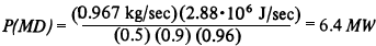
Approximately 2.2X 10⁹ W-hr
are required during each lunar day for mass driver operation. It is
clear that the mass driver control system must be designed to
accept a continuously changing launch rate of payloads in-order to
avoid the penalty of very large power smoothing units. Base
operations are anticipated to require the following units of power:
Habitat ~(16kW/person, 10 persons) 160 kW; trucks ~ 250 kW; sieving, packaging, and
maintenance facility and miscellaneous power requirement ~ 400 kW
for a total continuous input of P(B) = 800 kW. About
5.4X10⁸ W-hr of electrical energy
are required for operation of the base, exclusive of the mass
driver, each lunar month. This corresponds to 20 percent of the
total monthly power input of the solar array. Thus, the average
daytime power requirement is Po =
7.2 MW, whereas the nighttime requirement is about an order of
magnitude less at P(N) = 0.8 MW.
It is assumed that the power will be provided by a solar cell array (E = 0.1 efficient in solar to electrical energy conversion efficiency including power conditioning; 15 tons/MW area power density). Two innovations are suggested to minimize the size of the solar array and the capacity of power storage devices (e.g., fuel cells, flywheels). First, the solar array will be surrounded on three sides by three lightweight mirrors which are independently adjustable from the horizontal to 45o local vertical. These mirrors are of width equal to that of the side length Ls of the square array and a length of h = 1.414 Ls . Second, two to three orbiting mirrors will provide reflected sunlight during the lunar night adequate to operate the base (0.8 MW), but not the mass driver. By the third year of base operations, these orbiting mirrors (solettas) can be increased in size by a factor of 9 using fiberglass and aluminum from the SMF; this will permit operation of the mass driver during the lunar night and thus increase the mass ejection capacity of the base by a factor of 2 with little or no additional ground installations.
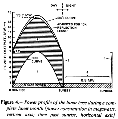
Figure 4 depicts the power
profile for the solar array/ mirror system augmented by soletta
illumination at night. Region 1 corresponds to a sine dependence of
the power output of the flat solar array, between sunrise and
sunset. The total watt-hours (WH) output in region 1 is
(2/ )PoLd
(length of lunar day) where )Po =
7.2 MW. Actually, the sine distribution of output power would not
be realized due to increasing external reflection and scattering of
the incident sunlight back to space as the illumination angle of
the solar cells approached the horizontal (0o). However, use of the mirrors greatly improves
the power input because the sunlight is then never incident on the
solar cells at less than 45o.
Continuous adjustment of the elevation angles of the mirrors on the
western and eastern edges of the solar array allows the reflection
of sunlight onto the array to produce additional power in region 2.
Lunar reflectors are effective whereas times-2 solar concentrators
are not competitive with solar cells alone for space power stations
since they can be continuously directed toward the Sun (ref. 16). The Lunar case is different in
that the "times-2" concentration need only occur (optional) about
lunar noon. Otherwise, the concentrators suggested here simply
maintain the solar radiation to the solar array at a high value
(
)PoLd
(length of lunar day) where )Po =
7.2 MW. Actually, the sine distribution of output power would not
be realized due to increasing external reflection and scattering of
the incident sunlight back to space as the illumination angle of
the solar cells approached the horizontal (0o). However, use of the mirrors greatly improves
the power input because the sunlight is then never incident on the
solar cells at less than 45o.
Continuous adjustment of the elevation angles of the mirrors on the
western and eastern edges of the solar array allows the reflection
of sunlight onto the array to produce additional power in region 2.
Lunar reflectors are effective whereas times-2 solar concentrators
are not competitive with solar cells alone for space power stations
since they can be continuously directed toward the Sun (ref. 16). The Lunar case is different in
that the "times-2" concentration need only occur (optional) about
lunar noon. Otherwise, the concentrators suggested here simply
maintain the solar radiation to the solar array at a high value
( 1 solar constant)
throughout the lunar day. Let E(=O.I) be the conversion efficiency
of solar energy into electrical output of the array and allow for
10 percent average reflection losses (c) at the mirrors and
the surface of the solar array, then we can estimate the area
(As) of the solar array (where
Ps = 1.4X 10³ MW/km is the solar constant) to be:
1 solar constant)
throughout the lunar day. Let E(=O.I) be the conversion efficiency
of solar energy into electrical output of the array and allow for
10 percent average reflection losses (c) at the mirrors and
the surface of the solar array, then we can estimate the area
(As) of the solar array (where
Ps = 1.4X 10³ MW/km is the solar constant) to be:
 [1 + (1 - c) (2 / )] E
For the stated values of the quantities in the equation we have
The mass of the solar array would be 108 tons. The mass of the three adjustable mirrors, support beams and hoisting mechanisms would be about 18 tons (E. Bock, Convair, San Diego) using two compression beams and side beams for each mirror and cable hoists. Reflectors are useful for power conditioning on the lunar surface, in spite of the large area of the reflectors, due to low gravity and lack of weather and weathering effects. This approach would be impractical terrestrially. Major future considerations in evaluation of this approach are (1) effects of running the solar cell array at two solar concentrations for about 1/4 of the lunar day and (2) conditioning of the front surface of the solar arrays to minimize reflection of sunlight at small angles of incidence. Alternatively, it may be advantageous to center-mount the array (or a segmented array) on a tower of height one-half the length of the array and point the array continuously toward the Sun or the particular soletta providing night-time illumination. Use of a tower would allow the solar cells to operate at lower temperatures during the lunar day.
Region 3 (sunrise and sunset) corresponds to either the east or
west mirror viewing the Sun while the general terrain is dark. Some
power can be received during this time due to the slow rotation of
the Moon and the large height of the mirrors
(Lh 260 m). The time interval
(ti) between sunset at the base and
the top of the mirror at the equator for a spherical moon is given
by
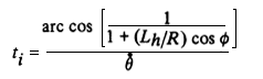
where  ~
0.53o/hr is the rotation rate of
the Moon, R = 1738 km (radius of the Moon),
Lh is the vertical dimension of the
array, and
~
0.53o/hr is the rotation rate of
the Moon, R = 1738 km (radius of the Moon),
Lh is the vertical dimension of the
array, and  the angle
of the mirror with respect to the direction to the local sunset
direction (=45o). Thus, for
Lh 260 m we have
ti = 1.57 hr. The pre-sunrise and
post-sunset operations can add as much as
the angle
of the mirror with respect to the direction to the local sunset
direction (=45o). Thus, for
Lh 260 m we have
ti = 1.57 hr. The pre-sunrise and
post-sunset operations can add as much as
0.11X10o).Large elevation difference are available in the lunar highlands. It is not unreasonable to expect that one could locate mountain peaks within 30 km of the base site which might be 2 km higher than the base. The peaks would be exposed to the Sun at least 5.2 hr longer than the base and possibly much longer if the local eastern and western horizons are significantly depressed below the horizon of the spherical Moon. Reflectors on the scale of 600 in (length) by 300 in (height) adjustable over 95o azimuth could contribute at least 0.74X10o to the night-time power budget or increase the operating time of the mass driver by 3 percent or more. Such surface mirrors could contribute 2 percent to 14 percent to the estimated nighttime energy budget of 2.7X 10o indicated as region 4 in figure 4, depending on local geometry.
An interesting option to conventional solar cells may be available for use on the Moon by using photoemission and/or thermionic emission. The basic power unit would consist of three aluminum strips which could be vapor deposited on the bottom and sides of a rectangular trench (possibly 3 or 4 cm wide and deep, and about 1 m long). The trench, one of tens of thousands of identical closely spaced trenches, would be oriented with its long axis in the east-west direction. The bottom of the trench would next be evaporatively coated with a photoemissive/thermionic material. Sunlight would produce a flow of electrons from the trench bottom to the sides evoking a small potential difference which can be regulated to control the current flow and thus maximize the power output. The mass of the aluminum and electron emissive materials required would be trivial compared to the equivalent areal mass of solar cells, whereas the mass of ancillary parallel and series hookup wire and power conditioning equipment should be similar to that needed for solar cells. Conversion efficiencies of about 5 percent are thought to be possible (ref. 17). This photo-similar effect is likely to operate naturally on the Moon in the levitation of lunar dust (ref. 18, 19). Further experimental and theoretical research is needed and should be given high priority for application not only to lunar surface operations, but also for possible space power systems which could be constructed largely of lunar materials.
As noted earlier, about 400 tons of power storage units (1.2-1.5 kW-hr/kg) would be required to power the station over one lunar night. In addition, about 300 tons of propellant would be required to soft-land the extra mass. Finally, as base activities increased, the storage capacity would increase linearly with the scale of nighttime operations. Total mass of power storage units could approach 6000 tons on the lunar surface and 4000 tons of propellant in LLO for delivery. For these reasons, the alternative approach of deploying large mirrors in lunar orbit which could power, illuminate, and warm the base at night and permit 24 hr a day operation even during the lunar night, is suggested.
Billman et al. (ref.9) and Ehricke
(ref.8) both proposed that large mirrors
be orbited about the Earth to illuminate cities, agricultural
regions, ice fields blocking navigation, and solar power
installations. Orbiting mirrors are far better suited for lunar
than terrestrial use due to the absence of a lunar atmosphere,
availability of continuously illuminated lunar orbits, the long
period of such lunar orbits, relatively small change in slant range
during the illuminating period, and the option of precessing the
apolune of each mirror over the cycle of the lunar month in order
to keep the apolune over the longitude of the lunar base (David
Ross, Stanford Univ., Aeronautics and Astronautics Dept., personal
communication). The amount of reflective area required in space is
independent (to first order) of the altitude of the solettas for
continuous coverage. The fundamental design constraint is that the
minimum size of spot (Ds) on the
ground is determined by the angular size of the Sun ( 9.3X10⁻³ rad)
and the slant range (h) between the orbiting mirror and the ground
spot where Ds = h.
9.3X10⁻³ rad)
and the slant range (h) between the orbiting mirror and the ground
spot where Ds = h.
The mirrors must be constructed of individual flat segments or
submirrors which must be individually directed toward the desired
ground spot. Submirror size is limited by the required flatness of
the mirror surface. The segments can be directed toward a reference
laser beam at the receiving site. For one solar constant of
illumination the mirror must be the size of the ground spot;
therefore, the diameter of the mirror
(DM) will also be
DM = h. In the lunar case the use of the three
movable mirrors on the ground (or a tilting solar array) which
surround each solar array will permit considerable smoothing and
effective concentration of the solar power to the array in response
to non-normal incidence of the sunlight reflected to the site by
the orbiting mirrors. The three ground mirrors become more
effective as the maximum viewing angle of the orbiting mirrors
above the local horizon increases. Use of ground mirrors or tilting
arrays avoids increasing the size of the orbiting mirror above
DM = h. However, attention must be given to array
spacing on the lunar surface as the ground installation grows in
order to insure that there is no significant shadowing of portions
of the array by foreground units.
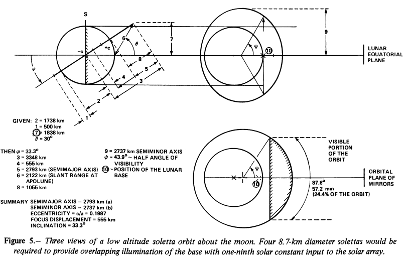
The suggested lunar system consists of four solettas trailing each other along a high inclination, low altitude orbit. It is assumed the initial solettas are sized to provide one-ninth solar illumination (average) to the arrays to power the lunar base through the night. These one-ninth solettas would be constructed in low-Earth orbit from components supplied from Earth. Figure 5 depicts the low altitude, high inclination orbit. In this example, the average slant range is 2800 km and Ds = DM = 26 km. For the initial one-ninth solar illumination at the base Ds = 8.7 km. A slight increase of the eccentricity of this orbit would permit overlap of the viewing periods (57.2 min; 24.4 percent of the orbit). Decreasing the inclination of the orbit increases viewing time but also the slant range to the base and therefore requires an increased mirror size.
Four mirrors, each about 40 km2 area (240 tons per mirror at 6 g/m2), could meet the overnight power needs of the base and prevent the extremely prolonged cold soak of lunar night by providing one-ninth the full solar constant. For an orbit with a perilune of 500 kin, apolune of 1610 km, and inclination of 33.3o , each mirror would rise in the southwest (or northwest), attain a maximum elevation of 20o in the south (or north), set in the southeast, and be visible above the horizon for 57.2 min per orbit (24 percent of the 3.9-hr orbit). The projected spot from such a satellite would be extremely elongated due to the low sighting angles. However, the three ground mirrors could be continually reconfigured to reflect soletta light into the collecting array thus obviating the low illumination angle. Assuming the launch costs ($650/kg) to an Earth orbit of altitude greater than 1000 km dominate the production and assembly costs of the mirrors, an investment of $624 million would be required for the initial orbiting network. This cost could be reduced sharply by utilizing the aluminum in shuttle tanks in the mirror structure. Savings in base construction time, continuous equipment usage, and minimization of power conditioning and storage should justify the expense. The mirrors would transport themselves by solar sailing from Earth orbit to low lunar orbit and might be used to transfer significant payloads as well to lunar orbit depending on the time constraints. It will be necessary to continually track and solar-sail the solettas. There must be a continual reconfiguring of the individual submirrors during the lunar daytime portion of the orbit and when the base is on the day side in order to utilize solar pressure to maintain the proper orbital elements. Presumably this can be a highly automated process.
NASA programs for solar-sail development have established the
characteristics of a large space mirror constructed out of aluminum
and plastics which could be deployed in the mid-1980's. Areal
densities as low as 6g/m2 can be
expected (refs. 20-22). Thus, one
low altitude soletta providing full solar illumination at the lunar
surface would have a mass Ms = (6
tons/km2)(/4)(26 km)2 =
3185 tons. Extensive use could be made of fiberglass and aluminum
from the initial production runs at the SMF to produce the full
size solettas for final production expansion of the lunar supply
base. If a technique can be developed to produce thin-film aluminum
without a substrate, then very little material would have to be
brought from the Earth. The solettas could be sailed directly from
the SMF to lunar orbit without the expenditure of reaction mass or
energy.
The relative efficiency of the solettas in providing energy increases as the size of the lunar base increases to fill the 26-krn diameter of the minimum illuminated spot. The initial installation on the lunar surface utilizes only 9XI0-5 of the incident sunlight and the 600,000 tons/yr installation 2XI0-3 of the incident sunlight. Thus, a soletta system could support the ejection of up to 3.4X10⁸ tons/yr of lunar material with a base installation of 45 to 50 percent less total mass than without the orbital reflector system.
CONCLUSION
Construction of a lunar supply base in support of suggested scenarios for space manufacturing (refs. 23-24) does not appear to present insurmountable problems. The main challenge is in reducing the overall costs, development and deployment times and designing highly automated systems capable of maintaining continuous high throughput of soil into space. The main research items are in the direction of enhancing rather than enabling base deployment and operation. Specific research and development objectives include the following:
|
Curator: Al Globus If you find any errors on this page contact Al Globus. |
 |
This site was hosted by the NASA Ames Research Center from 1994-2018 and is now hosted by:
